

3D printed planar biaxial device for imaging
OVERVIEW
My senior design team partnered with a research lab at UCSD. Part of their work involves stretching right ventricle samples from rats to evaluate how the collagen fibers rearrange over time through cyclic loading. The goal of this project was to design and assemble a 3D printed device capable of biaxially stretching right ventricle rat samples to match physiological conditions and image them under a multiphoton microscope.
RESPONSIBILITIES
I spearheaded the maintenance of the CAD parts and wider device assembly in SolidWorks. I ideated and designed several mechanisms utilized in my team's final prototype. I was also heavily involved in the prototyping process.
SKILLS
SolidWorks (FEA), SLA & FDM 3D Printing, Rapid Prototyping, Design Testing
PROJECT RUN
September 2021 - April 2022
background
Imagine making a list of worst case scenarios for a project, and they all happen. Well, that happened to me. Maybe I'm being a bit dramatic, but let me explain. At the beginning of my senior design project, our team talked through things that would put our project at a major standstill until resolved. While we laughed in the midst of writing these seemingly implausible scenarios down, that laughter quickly turned to uncertainty as each scenario became a reality. From a $500,000 microscope breaking without possibility of repair, to 3D printing malware holding our prototyping timeline back a couple of weeks, it seemed like things kept going wrong for me and my teammates. Regardless of these challenges, this year marked a time of immense growth for me as an engineer and as an individual. This project taught me to be flexible, creative, and resilient.
My senior design team partnered with the DVJ Lab at UCSD. Part of their work involves stretching right ventricle samples from rats to evaluate how the collagen fibers rearrange over time through cyclic loading, just like the body would experience during the cardiac cycle. When we were paired with their research group, they had a mechanism capable of stretching the tissue samples to match loading under physiological conditions. They also had access to a multiphoton microscope capable of imaging collagen fibers. However, there was no method of imaging the samples in their stretched configuration. The objective of the project was to design and assemble a 3D printed device capable of biaxially stretching right ventricle rat samples to match physiological conditions. Once the samples are stretched, the device must allow these stretched samples to be imaged under a multiphoton microscope.
starting with a major bottleneck
My team and I explored many options throughout the prototyping process. The first more obvious option was to create a device capable of stretching the tissue and being put under a microscope for imaging. This would allow the lab members to observe the collagen structure while the samples are stretched. However, our team ran into one major bottleneck in the first quarter of the project: the microscope we were expecting to use broke. Since a new one costing $500,000, was not going to be fixed. For a few weeks, we did not know if the focus of the project would shift and we were left at a standstill.
Finally, the PhD student that we were working with found another multiphoton microscope in a different lab that we could use. After completing a tour of the microscope with one of the lab members, we noted several things about the microscope that could become potential issues:
-
The microscope objective lifted less than an inch from the microscope platform at the most.
-
The back section of the microscope platform did not have sufficient space.
-
The new microscope was a water-immersion lens, and oil is placed between samples and cover slips.
-
The laser must be able to completely run through the sample.
-
Microscopes are expensive and a novel prototype could potentially be a liability.
my team's solution
With the different constraints set forth by our transition to a new microscope, my group pivoted to a different solution. Rather than having a biaxial stretching device that can be placed under the under microscope, we decided to create a device that stretches the tissue and submerges it in a fixing solution for 48 hours. After this period, the tissue sample would be fixed in its stretched state and then taken out of the device for imaging.

final
prototype

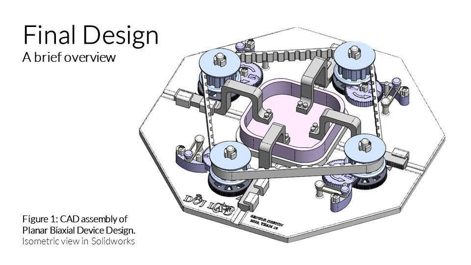
The device has three major functions: 1) secures and submerges tissue samples, 2) stretches the samples in small increments, and 3) locks the tissues in their stretched state for the tissue fixation process.

The device begins with a base with the appropriate spaces, posts, and rails for each device component. The bath that the tissue sample will sit in is removable and can be placed in the center of the device.

The base of the device was printed using FDM techniques and is made of ABS plastic. The other pieces were printed using SLA techniques and are made of resin. The timing belt was purchased separately.
The device has three major functions: 1) secures and submerges tissue samples, 2) stretches the samples in small increments, and 3) locks the tissues in their stretched state for the tissue fixation process.
the design process
discover
define
ideate
prototype
testing
literature review
mentor interviews
problem statement
functional requirements
goals and constraints
design sketching
alternate design matrix
cardboard mock ups
CAD design & analysis
3D printing parts
prototype assembly
material testing
expected load testing
displacement testing
As shown in the diagram above, the design process for this project included five major stages: discovery, defining, ideating, prototyping, and testing. Some of the initial sketches, cardboard prototypes, and printed prototypes that I worked on during the duration of the project are included below.
my initial sketches


layered device concept (side)
rack and pinion mechanism #1 (top)
rack and pinion stretching mechanism #2 (top)
rack and pinion mechanism #1 (side)
I created these basic sketches at the start of the prototyping process to brainstorm possible device designs. My designs centered around the biaxial stretching component of the device, since I considered this the most difficult part to design. I used these sketches to collaborate with my teammates and communicate my designs to my mentors.
my cardboard prototype

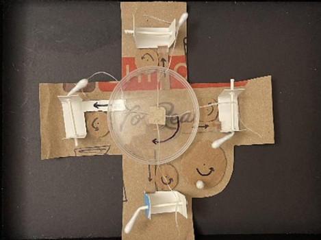
rack and pinion mechanism #1
(top view)
Once the design sketches were being finalized, our team created several cardboard mockups to present to our mentors. This allowed us to describe and demonstrate in detail what we pictured for the device. The cardboard model that I created is shown above, where the arrows indicate which way the different parts will move.
3d printing and prototyping parts


SLA Printing (formlabs Form 3+)
FDM Printing (Lulzbot Mini & Prusa i3 MK3)
After the sketches and prototypes, the fabrication phase of rapid prototyping was underway. Different device pieces and partial mechanisms were designed in SolidWorks. These parts were 3D printed using resin and FDM printing techniques then evaluated for different functions, like load bearing and material interactions. The process of CAD design, printing, and testing continued across several months. A glimpse at the printing process is shown in the images above. Details of the mechanisms that I designed in SolidWorks are described in the following sections.
designing CAD parts for the device
My three biggest design contributions to the project involved the following:
-
Creating a gear train to stretch the tissue in 0.3mm increments
-
Developing the arrangement of the device's different sub-mechanisms
-
Breaking up the base into sections for 3D printing
1. achieving small increments of stretch
MOTIVATION
One major challenge of this project was determining a device design capable of stretching the tissue samples 10% of their original dimensions, or 5% on each side. The tissue samples averaged dimensions of roughly 6mm each, meaning the loading arms would needed to be capable of moving 0.3mm respectively to achieve overall 10% stretch.
MY SOLUTION
One of our mentors stated that it would be convenient to have some component of the device to turn in order to move the loading arm back the appropriate amount. Immediately, my mind went to mechanisms that convert rotational motion to translation motion: a rack and pinion. I created several sketches for designs based around this concept, as shown previously. This concept was carried over into the final design, where the loading arm is the rack and two gears in series act as the pinions. When the user turns the smaller gear, this causes the larger gear to turn and the loading arm to move. I downloaded open source CAD parts from manufacturers online, scaled them down to the appropriate dimensions, and created custom parts for each mechanism.


The first image above shows a top view of the rack and pinion mechanism combined with the ratchet and pawl. The ratchet wheel and the small gear are printed as one piece. The ratchet wheel section is transparent in this top view to show how the small gear makes contact with the large gear. The placement of the wheel allows it to make contact with the pawl, turning in tandem with the small gear, and operating without interfering with the rest of the rack and pinion mechanism. The second image shows another angle of the mechanism without the transparent wheel.
2. organizing the sub-mechanisms
MOTIVATION
Prior to printing the entire device, our team did partial device prints to test that the components printed at a proper resolution and performed as intended. We did test prints for the rack and pinion mechanism, ratchet and pawl locking mechanism, and locking pin. During this process, our team considered different ways to organize the mechanisms and allow them to work in tandem with each other.
MY SOLUTION
I sketched out several different methods of arranging the device components. This sketch was taken to SolidWorks, where I revised existing pieces from the assembly and created new pieces to match the new design. The mechanisms are layered as follows: the rack and pinion on the bottom, the ratchet wheel and pawl in the middle layer, and the large gear for the timing belt on top. The ratchet wheel and the smallest gear on the rack and pinion mechanism were printed as one piece. The large timing belt gear and the larger rack and pinion gear were printed as separate pieces, but have sections that fit together and allow them to rotate together.


Pictured above is the initial sketch that I created for the device (left) and the prototype that was printed and used for partial device testing (right).
.png)

.png)
I have provided a sequence of partial device assemblies above to see in detail how the pieces are stacked. The order starts at the left, where the rack and pinion starts at the bottom. The ratchet wheel and pawl are placed on top, where the wheel and the small gear are one piece. Finally, the large timing belt gear in blue is fit to the top section of the large gear in black. This allows then to move together and can be disassembled after testing.
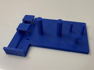
3. sectioning off the base for printing
MOTIVATION
Once the base design was finalized, it was evident that the piece was too large to be printed as one piece with the printers available to us. We needed to split the base into several pieces that could be printed separately then fit together afterwards. The pieces would eventually be held together with glue.
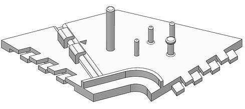
MY SOLUTION
After checking the dimensions on the 3D printers available to us, I decided to divide the base into four identical pieces. Inspired by finger joints used in woodworking, I designed a two layer finger joint edge on each of the base parts. This design would minimize degrees of freedom both parallel and perpendicular to the edge of each piece prior to gluing. The pieces are joined together to create the base seen in the SolidWorks renderings and final prototype.
_edited.jpg)

This aspect of the design was fairly difficult to fabricate. The resin printer was more accurate in reproducing the dimensions specified in SolidWorks. However, larger pieces tend to warp after the curing process. Rather than the pieces being flat, they each had a slight curve. This made it very difficult to fit the pieces together. Meanwhile, we turned to FDM printing which had no issues producing a flat piece. However, the tolerance range for aspects of the device are small and the FDM printers could not accommodate the intricate details as originally designated in the CAD files.