

3d printed coin weight boats
OVERVIEW
My senior design team needed to do fixture testing for our device but didn't have consistent access to standardized hanging weights. I decided to design coin holders capable of supporting six quarters over several loading trials. I utilized FEA on SolidWorks to predict prototype behavior and iterated on my initial design. I reached a final version after my second iteration.
SKILLS
SolidWorks, FDM 3D Printing, Rapid Prototyping
PROJECT DATE
April 2022 - May 2022
my initial thoughts
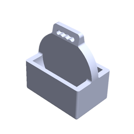
When I didn't have access to a needed testing tool, I decided to make one. During my senior design project, the lab we worked in didn't have standardized testing weights on hand. We could have borrowed weight sets from other labs, but I decided it may be inconvenient to keep going back and forth taking the weights in case we needed to repeat testing at some point. I realized that we did have standard weights on hand that could do the job; coins! The device components that we needed to test on didn't require large loads, since the components were small. I decided to design a weight boat that could hold six quarters at most, or 34.02 grams, and had a handle at the top to tie a string or rubber band.
This wasn't a part of the device we were designing, and definitely wasn't something that was in the project description. However, I decided that this would be a major asset to our testing practices. I enjoyed having agency of identifying additional problems not only with our device design, but also our device testing methods and executing them freely. This project-within-a-project presented me with a nice opportunity to practice a lot of different skills: problem solving, 3D CAD design, FEA, and rapid prototyping. I was enthusiastic and prepared to create something that would fulfill all of our testing needs.
designing the boats in solidworks
To begin, I measured the diameter and thickness of a quarter with calipers. Following this, I created a sketch in SolidWorks starting from a circle with a diameter equivalent to a quarter. I offset this diameter as a starting value for the diameter of the coin space then added a handle and hook design to the top of the circle. I used the Boss Extrude tool to create the center section of the boat. On one of the flat surfaces, I created a sketch and extruded the features to create the bottom and sides of one side of the boat. I made one more sketch on the and extruded the shape to create a wall and close off the coin space. On the other side of the part, I used the Mirror Part tool to make the two sides of the part identical.
printing the boats
I created the prototypes using a Prusa i3 MK3 3D Printer and printed them using PLA. The boats were oriented with the bottom of the boat making contact with the build plate. I made sure to double check that the towers option for supports were not checked off. I have printed with this particular printer before, and the towers can be difficult to remove. In this case, supports are needed for the handle since there is overhang. Using towers would make it possible for the entire handle to come off during support removal, so changed it to zig zag supports. All of the default settings for the print were kept the same. After the print was complete, I proceeded and used the coin boats for fixture testing.
theoretical testing: FEA in solidworks
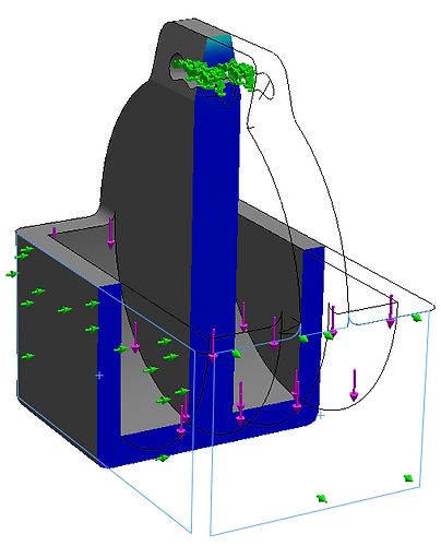
Prior to printing the boats, I performed a Finite Element Analysis (FEA) in SolidWorks to see how the boat would withstand expected loading values. I defined the material as PLA then started a new Study. I added Fixtures to the part starting with a Fixed Geometry at the surface that the boat will be hung from. I operated under the assumption that this would analyze the behavior of the boat while hanging completely vertical with no external forces causing it to sway back and forth. With this in mind, I added Sliders at the sides of the coin boat. I added an External Load to the inside surface of each coin space equivalent to the force three coins due to gravity, or 0.167 Newtons. Lastly, I created a Mesh to break the part up into a sufficient number of finite elements which I define as at least three two units spanning the smallest section of the part.
.png)
I ran the study and observed the stress and displacement concentrations on the piece in response to loading. Prior to this, I knew that the handle would experience the highest stress concentration and the highest likelihood of failure. With the first prototype, it was clear that under ideal conditions, the part would not fail with an incredibly high 205 factor of safety. Of course, this is simply under very specific circumstance. Following this, I printed the first prototype and experimentally tested it by placing three quarters in each boat pocket and hanging the boat from a string for a 72 hour period. This was successful, but I wanted to iterate on the design to cut down on printing time and use less material that is unnecessary to the function of the piece.
After this, we needed more than one. I adjusted the design to an open hook handle rather than a fully closed off handle like in the first prototype. With the next iteration of the prototype, I ran an FEA with the same fixtures and external forces as the initial study. The results also indicated low likelihood for failure, so I printed it and loaded it in the same manner as the first; the test was successful. For my third print, I decided to make some last adjustments to the design by eliminating unneeded corners of the boat and including cutouts to remove material. I ran one last FEA study, printed it, and tested it. Like the others, successful.


experimental testing: fixture hanging
A partial section of a device prototype was fixed vertically using a clamp and ring stand. The boats were filled with six quarters, and string was looped through the handle to hang them from the device fixture. The first boat prototype was hung for ~72 hours and did not experience any changes in its structure.
