
robotic arm for team competition
OVERVIEW
My team of four was tasked with creating a robot capable of maneuvering a competition field, picking up acrylic pieces, stacking them, and pressing a button all within 60 seconds.
RESPONSIBILITIES
I spearheaded the design of the middle joint in the robotic arm through a gear train design meeting necessary maximum load and rotational speed functional requirements. I iterated on the component design and verified experimental performance to theoretical performance values. I also contributed heavily to concept sketches and prototyping.
SKILLS
Autodesk Inventor, AutoCAD, Laser Cutting, Shop Tools, 3D Printing, Rapid Prototyping
PROJECT RUN
October 2019 - December 2019
background
Who would've thought that laser cutting acrylic for six weeks would be a turning point for me? UCSD's Introduction to Engineering Graphics and Design course hosts a robot competition every fall and spring quarter where teams are tasked with designing a robot capable of maneuvering a competition field and completing different tasks under a time limit. The majority of this class involved teams working in a shared engineering space outside of classroom hours multiple times a week. During this time, I would work with my own team, iterate on different component designs, and experience camaraderie with fellow engineering students to name a few. To this day, this was one of the most time consuming courses I had taken during my time in undergrad. However, it is one of my favorite classes, if not my favorite. This class introduced me to the world of engineering design, rapid prototyping, and CAD software. Even in the midst of this experience, I knew was a turning point for me. For the first time since college had started, I identified something that I could see myself long after the class was over. What I felt was passion. I have been following that feeling ever since.
my team's solution
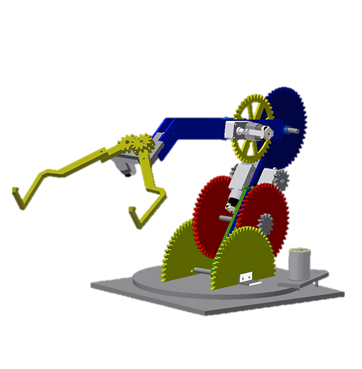
During my year, my team of four was tasked with creating a robot capable of picking up acrylic pieces, stacking them, and pressing a button all within 60 seconds. Additionally, the robot was required to fit in a 10x10x10 inch box. Our team designed a stationary robotic arm with a rotating base, two gear-driven joints, and a claw made to wrap snuggly around the acrylic stacking pieces. The robot assembly from Autodesk Inventor is labeled and included below.

The robot is screwed to the center of the competition field. The rotating base brings the robot in the direction of the desired piece, while the two joints are controlled to extend the arm to the appropriate position in front of the piece. The claw starts in an open position, and closes around the piece's neck. From here, the robot adjusts to place the piece in the stacking zone. For more details on the competition, visit the MAE 3 robot competition website.
rotating base
claw
gears
designing the middle joint of the arm
As a team, we decided to create a robotic arm for our overarching robot design capable of unraveling at the start of the competition and extend to reach and stack pieces. Knowing that we would need a mechanism that could provide a sufficient amount of torque in response to loading, I decided to create a gear train nested within the middle section of the robotic arm to provide the robot with appropriate reach, rotational speed, and appropriate load bearing capabilities.
Teams were provided with various gear sketch files with different numbers of teeth. I acquired three gears: 12 teeth, 40 teeth, and 48 teeth gears. I opened each of these sketches in Autodesk Inventor and used the Extrude tool to create 3D parts with the same thickness as the material that I planned to use, 1/8 inch acrylic. For the 40-teeth gear, I decided to add some cutouts using Extrude Cut to reduce the overall load that the gear train would have to support. Following this, I moved these parts to the larger robot assembly to see how the gears would interact with the other parts of the robot. A general layout of the middle joint is shown in the image below.
After seeing that the parts would not interfere with other sections of the robot, I imported these files to AutoCAD. I utilized the Explode tool to break the part region into individual segments and evaluate if there are any unneeded segments or loops that needed to be closed. This was a crucial step because the laser cutter that I had access to is not capable of reading regions for cutting. From here, I downloaded the completed dxf files and saved them on a flash drive for laser cutting. I used a LaserCAM 100 Watt CO2 Laser Cutter to cut the pendulum and escapement wheel out of 1/4 inch acrylic. Following this, I added my pieces to the robot and worked through robot testing and design iterations.

initial sketches and design concepts
.png)
.png)
.png)
.png)
The prototyping process started with me and my teammates creating basic design sketches and describing our individual visions for the robot. Four of the sketches that I presented are shown above. Our final prototype ended up aligning with the design in the top left corner, where a robotic arm pivots about a fixed point and reaches for different pieces through rotating joints.

Following the initial ideation stage, our group started to create detailed sketches for each section of the robot based on the material and manufacturing resources available to us. Pictured above is a sketch that I created for the robotic arm's base joint mechanism.


The sketches were translated to Autodesk Inventor, where each team member created the individual parts and subassemblies for the section they were spearheading. I created all of the parts for the middle section of the arm. Shown to the left above is a drawing of my component subassembly, where the major parts are listed in the bottom righthand corner. The image to the right shows a close up front view of the arm's gear train nested within the two robot arm pieces.
calculations and prototype testing
The prototyping stage was supplemented by free body diagrams and theoretical calculations, followed by experimental testing. I performed torque and speed analyses with each iteration of the design. This allowed me to determine appropriate component dimensions (i.e. gear sizes), design a gear train that produces appropriate torque for expected loading, and design a joint that rotates with sufficient time to maneuver the competition stage. An example free body sketch for torque and speed are shown below.


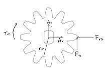

TORQUE ANALYSIS
For the theoretical calculations, I performed a torque analysis. I calculated the total output torque of the gear train, the moment generated by the robot's arm, and the moment generated by loads applied to the end of the arm. From here, I determined that this component of the robot was theoretically capable of producing 1.598 Newton meters of torque and supporting 1167 grams.
To determine the actual performance of the joint, the lower portion of the arm was positioned perpendicular to the base and contest table. The upper arm was set at an acute angle relative to the lower portion of the arm. From here, the upper arm was tested by lifting several loads. When the forearm is able to “lift” a load, it implies that the arm is able to surpass a 90° angle position relative to the lower portion of the arm. Testing was split into three section:
-
Being able to lift the forearm and claw unloaded
-
Being able to lift the forearm, claw, and saber piece
-
Being able to lift the forearm, claw, and some additional load, increasing the load amount until the arm stalls and cannot safely lift it up and place it down; this amount is the maximum load
After this, the maximum load was determined to be 650 grams, generating a torque of 0.8899Nm. This indicates a significant 44.3% error when compared to the theoretical values, and produces a 3.655 factor of safety when fully loaded. This number will be addressed in the discussion section below.
SPEED ANALYSIS
Following the torque analysis, I performed a speed analysis. I used the maximum power output of the motor and the maximum torque output from the torque analysis. From here, the angular velocity was expected to be 0.09229 radians per second.
The same testing conditions were utilized to determine the experimental angular velocity of the upper arm apparatus. The upper arm and base were parallel, while the lower arm was perpendicular to these two. I timed how long it took the arm to lift up and become parallel with the lower arm. I timed how long it took for the upper arm to complete a fourth of a revolution. This time allows us to calculate the actual angular velocity, 0.1199 radians per second. This produces a 0.30% error when compared to theoretical values.
DISCUSSION
The speed analysis was accurate while the torque analysis was not. After observing the robot perform numerous times, the numbers make sense. The joint produced a noticeable squeaking sound when rotating the arm upwards. I believe that this may have been the result of a CAD mistake, where the pitch circle of the gears were not perfectly coincident with each other when the gear placements on the arm were determined. In other words, two gears were placed too close together. This caused the motor to expend more torque overcoming the friction between these two gears. This project has taught me to be more careful about triple checking my CAD relations in assemblies.