

art vending machine @ UCSD
OVERVIEW
For this quarter-long project, my team aimed to streamline art small business owners to the wider UCSD community through a vending machine that showcases and distributes different creators' products.
RESPONSIBILITIES
I managed the design and assembly of the vending machine enclosure, shelving units, and clamps to attach the item coils to the machine's servo motors. I created wooden enclosure and shelving pieces via laser cutting. The custom PLA motor clamps were fabricated through 3D printing.
SKILLS
Inkscape, SolidWorks, 3D Printing, Laser Cutting, Basic Shop Tools
PROJECT RUN
March 2022 - May 2022
background
It's no secret; STEM-superiority has become a topic of discourse on college campuses. As a result, small art creators have been left out of the conversation, leaving their work generally underexposed and underappreciated. With a diverse and bright-minded community like the student population at UCSD, art creators are ready to have their work seen and consumed. One of my teammates noted this observation, adding that there are not many physical spaces that connect artists to individuals on-campus. With this said, my team's project aimed to streamline art small business owners to the wider UCSD community by showcasing and distributing different creators' products.
my team's solution
Our team decided to create a vending machine prototype that can be placed in a space on-campus. The machine will contain small arts and crafts products from small business owners at UCSD, such as stickers, keychains, and earrings. Products from different creators will be put on rotation in the machine. Since there are a limited number of shelves in the machine, a QR is included on the machine and brings users to a website that links to the products of different creators. With this solution, small art business owners gain exposure and a means of distributing work.
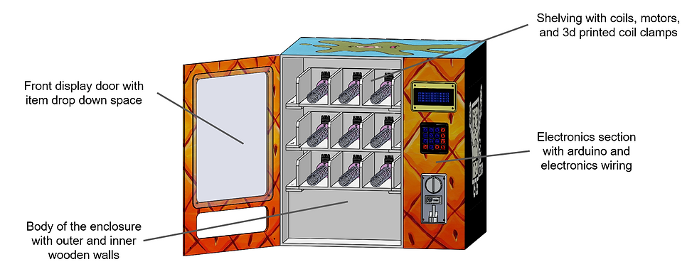
creating the enclosure and shelves
The vending machine required an enclosure to house the electrical components of the machine, and shelving units were needed to hold the vending machine's products. Each team was allocated a budget of $200, and most of the budget was already dedicated to the electronics of the machine. As a result, I decided to go with wood as my main material for the enclosure. I scavenged around different spaces on and off campus for enough material. Based on how much I could find, I determined appropriate dimensions that the amount of wood could accommodate, leaving spare wood in case extra was needed. An overview of the design is shown below.
.png)
I consulted MakerCase for laser cut box templates after deciding on initial dimensions. I was given three options for a basic box shape: simple flat edge joints, finger joints, and T-slots. Provided that the enclosure wood was 1/4 inch, I decided to choose T-slots to hold the top, bottom, and side sections of the enclosure together. I knew that I would want the option of assembling and disassembling the machine throughout the fabrication process, which neither of the other edge joint types offered. From here, I entered my external vending machine dimensions to MakerCase, specified material thickness and bolt information, and downloaded the box plans as DXF files. I opened the template in Solidworks eDrawings to evaluate the files, then imported them to sketches in SolidWorks. I used the Extrude feature to import the surfaces as 3D parts in the wider vending machine assembly to ensure that the dimensions were compatible with the different parts of the enclosure.
.png)
.png)
I prepared the enclosure pieces for laser cutting by creating svg files for the pieces in Inkscape, ensuring that the stroke color was red to indicate in the laser cutting software that I wanted to make vector cuts on my material. The enclosure pieces and shelf supports were made of 1/4 inch plywood held together with M6 screws, while the shelves were composed of 1/8 inch plywood held together with M3 screws. The material was cut using a Full Spectrum P-Series 42x36 Laser Cutter with a 90W CO2 Laser. Additional holes for the electronics were added following the laser cutting process using a cordless power drill with the appropriate drill bits. The last step of the assembly process was painting the machine; I decided to go with a Spongebob theme because, why not?
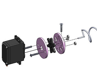
creating a custom clamp to connect item coils to servo motors
Our team decided to use 360 degree servo motors to turn the vending machine item coils. However, there wasn't a way to connect the coils to the motors. I noticed that the motors came with different attachments that snap into the motor shaft, including a six point star-shaped attachment. Rather than creating a part that connects the coil to the shaft, I created two piece clamp that connects to the shaft attachment instead. The clamp uses a screw to fix the straight end of the coil in place. There is a space for star piece the where the two piece of the clamp meet and hold it in place.
First, I went onto GrabCAD to download CAD files of the electronic components of the vending machine including the six point star attachment shown below. I evaluated different sections of the part file using the Measure tool in SolidWorks. I verified these dimensions by measuring the same sections of the attachment using calipers. From here, I copied the sketch of the star attachment and pasted it into the part files for the front and back pieces of the clamp. I used the Offset Entities tool to provide clearance for the piece to fit properly. I decided to use screws and bolts to hold the clamp pieces together as well as hold the coil in place. I consulted ANSI B4.2-1978 (R1994) charts for a general range for metric clearance holes.
The images below show the subassembly of the motor clamp, item coil, servo motor, star attachment, and screws. The center diagram includes labels to each major component. The clamp is transparent to show components nested within it. Exploded views are included on the left and the right, showing the interior of each motor piece.
.png)
_edited.jpg)
.png)
The clamp parts were 3D printed using a LulzBot Mini 3D printer. The front part of the clamp was oriented with the back contacting the build plate. Flipping the part 180 degrees would result in unnecessary supports for overhanging pieces, increasing the printing time. The back part of the clamp was printed with the space for the star piece oriented on top. I printed ten of each piece, the first being a test print. Once the prints were completed, edges were filed down to remove remnants of the raft and pliers were used to removed supports from the inside of the cover.
creating a custom cover for the LCD screen on the electronics front door
The LCD Screen included the text screen and the LCD controller board attached to the back of the screen. Since the board is larger than the screen, the edges are exposed. I decided to create a simple cover for the controller board to place on top of the LCD screen.
I started by using calipers to measure the needed sections of the LCD screen, most notably the length and width of the text screen, along with the holes at each corner of the controller board. I cross checked these measurements with given dimensions from the product itself for confirmation.


After this, I moved to GrabCAD and downloaded a CAD file for the screen. From here, I created my CAD part for the file. The part consists of two Boss Extrudes, the first being the front section of the cover that exposes the text screen, conceals the front of the controller board, and provides holes for the corner screws. Similar to my approach with the clamp design, I consulted ANSI B4.2-1978 (R1994) charts for a general range for metric clearance holes. The second Boss Extrude extends past the sides of the controller board and hides it completely from being seen. Finally, fillets were added to the edges of the front section for a cleaner look and to avoid scratching the user while handling.
The cover was 3D printed using a LulzBot TAZ 5 3D printer. The part was oriented with the back of the cover making contact with the build plate in order to minimize imperfections on the front. Initially, the cover had issues with adhering to the build plate but changing the plate adhesion setting from a brim to a raft seemed to do the trick. Once the print was completed, edges were filed to remove remnants of the raft and pliers were used to removed supports from the inside of the cover. From here, the LCD screen was placed in the cover and screwed onto the machine.
.png)
.png)